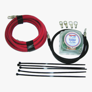
Installing a battery isolator in a bus optimizes the charging of both engine and house batteries. Positioned between these systems, it enables the engine to charge the house batteries when running, while solar power recharges the engine battery when the house batteries are full.
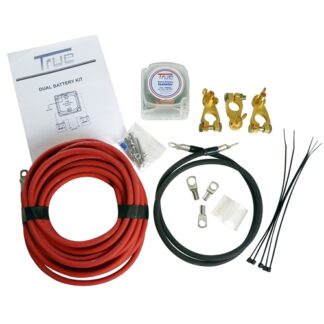
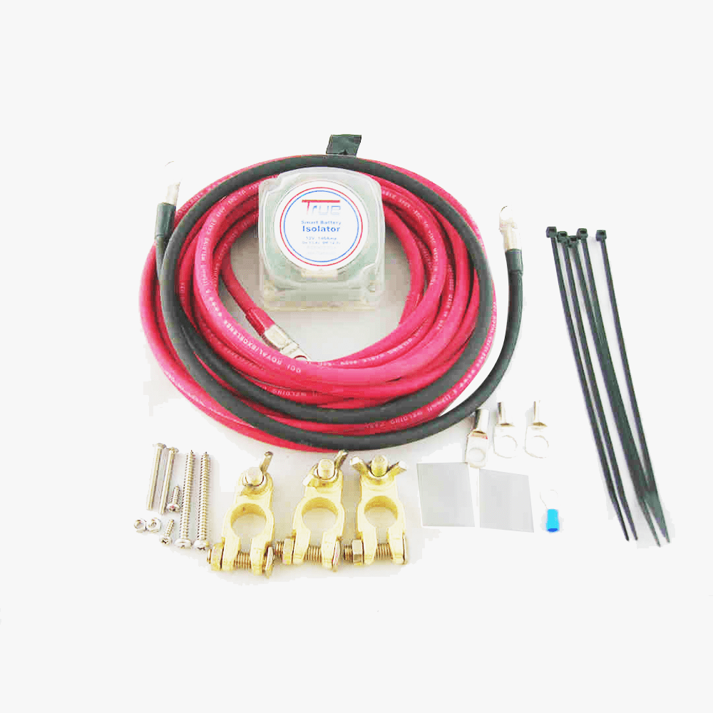
Wiring the system involves four-gauge cables and a grounding wire, connecting terminals securely. A switch adds manual control over the isolator for specific charging needs.
Once installed and tested, the system effectively manages energy, preventing engine battery drainage and ensuring consistent operation even during limited sunlight.
—————-
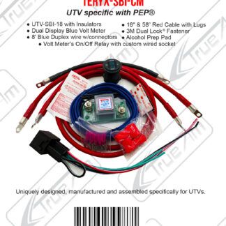
The isolator, purchased for $75, sits between the engine and house batteries in a bus. When the engine is on, it helps charge the house batteries, and when the solar system charges the house batteries, it can also charge the engine battery. This dual function ensures both battery banks remain charged and provides a convenient solution for maintaining battery power while using solar and engine charging methods.
The isolator is connected using two quarter-inch terminals, one for the engine battery and the other for the house battery. The setup uses four-gauge wire instead of the recommended six-gauge wire for a longer run between the engine and house batteries. The batteries are connected to a common terminal, making it easier to manage the connections and ensure proper charging between both battery banks. The batteries are housed in a compartment that allows convenient wiring for this system.
It sounds like you’re running a wire between your engine and house batteries and using thicker wire (4 gauge instead of 6 gauge) due to the long distance between the batteries. This setup will help ensure the connection is efficient and reliable, especially given the distance between the two battery compartments. You also plan to remove some components for better access and convenience while working on the system.
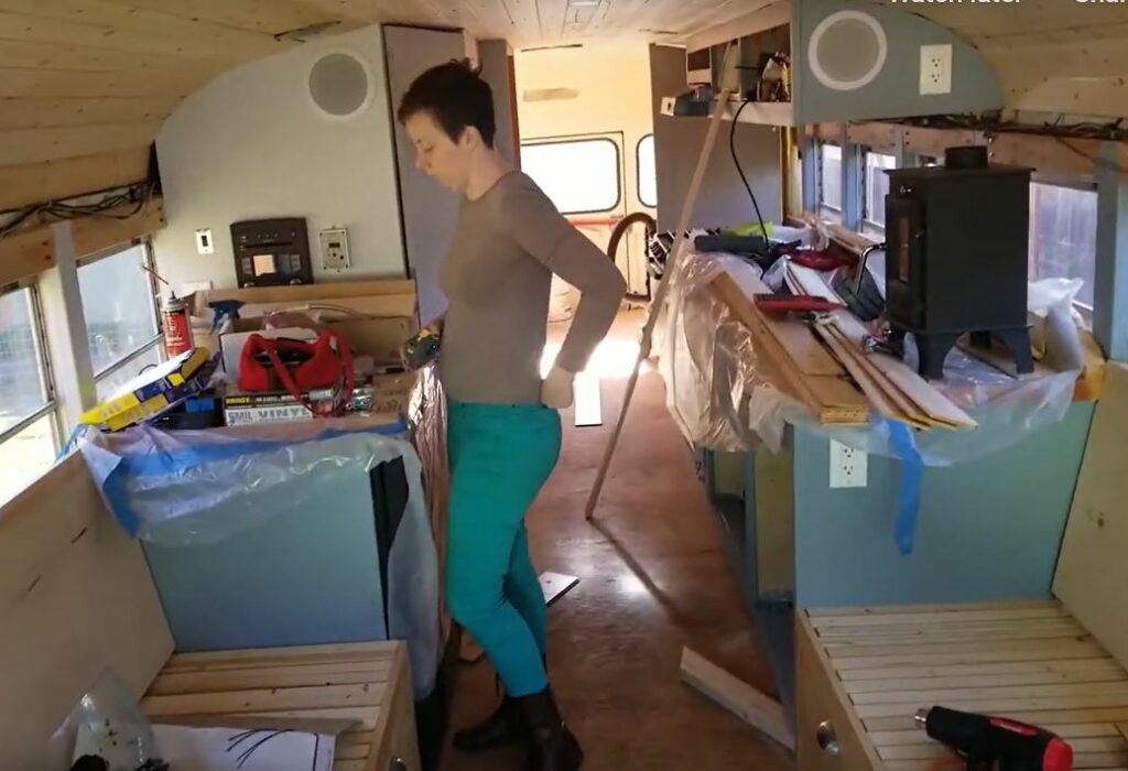
I’m down by my engine or my house batteries, which are in that closet over there, so here we go. I’m down by my batteries. There’s one in here and one in here; they both connect to a common terminal that’s located through those holes in the back there.
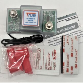
I positioned the battery isolator by twisting the battery in its compartment and drilling two mounting holes. The backplate was secured in place, ready for installation. The setup includes a grounding wire and a four-gauge wire to connect to the sense terminal, which corresponds to the engine battery.
I expanded the mounting holes to accommodate the four-gauge wire and prepared a grounding wire for installation. The isolator is now mounted, with terminals designated for the engine (sense terminal) and house batteries. The next step involves feeding wires through and connecting them to the positive terminals of both engine batteries. Work resumed the following day at the battery box to continue the setup.
I will attach a wire to the isolator for my other battery bank, which I hope will complete the system. The cables are connected: one for the house battery and one for the engine battery. Next, I need to secure everything in place and connect the house battery to see if the system powers on. The power is currently shut off, so I will connect the positive terminal now.
I connected the cable to the positive terminal, tightened it, and relocated the temperature sensor to another terminal to reduce congestion. The temperature sensor is non-electrical, so repositioning it won’t affect functionality. This completes the setup for this step.
After connecting everything, I prepared to test the isolator. The LED indicator only lights up when both battery banks are linked. To test, I needed either more sunlight to charge the house batteries or to start the engine to fully charge the starting battery. I reinstalled the battery while ensuring visibility for monitoring and planned to start the engine to verify functionality.
The engine failed to start due to prolonged inactivity, so I connected it to a charger to restore power. The isolator, when functioning properly, should prevent such issues by linking the house and engine batteries once charged. After charging, I started the engine, and the isolator began working, delivering 28 amps to charge the house batteries. This confirmed the system’s functionality in transferring power efficiently between the battery banks.

The engine battery is charging, and the system is working as expected. The isolator connects both batteries to the engine at 12 volts, with one wire leading to the engine and the other charging the house batteries. The RPMs are down as the cruise control was reduced, but the system is still functional. The setup ensures that the house batteries are being charged effectively, and the isolator’s role is confirmed as it manages power transfer between the batteries.
05:25
06:14
other wire which is just a grounding wire that I’ve grounded to the chassis over here and it needs that to function and if you put a switch in the middle of that circuit then you can turn the isolator on and off so the reason that I want to install a switch in the middle of this circuit for the ground wire so that I can turn the isolator on and off at will I would just like to have a little bit more control generally it’s going to stay on but you know to top off my batteries maybe it would be a better
The battery isolator in the bus has been working well. The user mainly keeps it off during winter due to limited sunlight but occasionally turns it on to let solar power charge the engine battery. They plan to manually control the circuit with a switch to better manage charging between batteries. The isolator helps charge both the engine and house batteries, and the user monitors its performance, especially during sunny weather.
The user attempts to start the engine after it has been sitting for weeks. They flip the battery isolator on, but there’s a 30-second delay before it activates. The engine doesn’t start immediately, likely due to insufficient battery charge. The user waits for the air compressor to reach the correct pressure level, which is necessary for the air brakes to function. They observe that the isolator may be taking longer to respond than expected, and they plan to monitor it further once the engine starts charging again.
The user suspects that the engine batteries aren’t as charged as they thought, so they shut off the engine and leave the isolator connected. They hope that with a full day of sunny weather, the batteries will charge. The next day, the user checks the isolator again, leaving it on for a day and a half. While it doesn’t guarantee activation, they confirm that the isolator is ready to connect the batteries when there’s enough charge.
The user checks the house batteries, finding 13.8 volts and 1.2 amps of charge, with the batteries being 98% full. They confirm that the isolator is working by turning it on and off. When the connection is closed, the amps rise to 6.2 from the solar panels, indicating that the system is charging correctly. This shows that the isolator effectively manages the charge from both solar and engine sources.
The user observes that with the isolator off and solar power on, the system is charging the house batteries at 14.6 volts. This proves that the isolator can successfully charge the engine batteries when it’s connected and receiving sufficient sunlight. After several days of testing, the user plans to test the system’s ability to charge in the opposite direction. The isolator’s function appears to be working well, managing both solar and engine charging.
After turning off the solar, the user flips the isolator on, triggering the connection between the house and engine batteries. This successfully starts charging the house batteries, confirming the isolator’s function. This test demonstrates that the isolator can manage both battery charging directions effectively, with the engine charging the house batteries and vice versa when necessary.